Smart Metering Systems
June 24, 2020Material Composition of Ball Valves
April 16, 2021PRV Selection in High-Rise Buildings – A Brief Walkthrough


Sanjay Jude
Director – Business Development
Lehry Instrumentation and Valves Pvt. Ltd.
Pressure Reducing Valves have been in use for various applications since the 19th century. The first PRV was about 2m high. Today, they fit right on the palm of a hand.
PRVs have become the heart of a plumbing system and their selection is extremely important. Apart from just the sizing criteria, that is covered later into this article, it’s first important to select the right type. PRVs mainly come in 2 types of constructions:
1. Piston Operated, and
2. Diaphragm Operated.
The Piston Operated PRVs consist of the old-school type of construction that primarily has a piston moving vertically up and down to compensate for pressure differential with a spring tension feedback on a metal disc. This type became infamous and was widely used in the past – successfully, but that has changed? The Demand changed it. By Demand here is meant the consumer demand in water systems that have changed greatly since 2010 in the country. With buildings getting higher and wider, the density distribution of apartments or consumption points has become much larger and that results in wide variations in demand through a single day.
As a result of varying demand, 3 main points arise.
1. Variating flow rates on the inlet side (mostly because Hydropneumatic pumps are used)
2. Variating inlet pressures
3. As demand increases and decreases, the pressure drop on the outlet varies in kind ???.
The above are basic resultants, but they matter a lot to the core functioning of a PRV. To meet the above requirements, a piston PRV has no mechanism to counter or utilise such variations. The Piston PRV manufacturers are aware that variations in inlet flow rates and pressure are going to cause erratic functioning in the PRV. There is also no mechanism for these PRVs to adapt to variating outlet pressures – causing a calamitous dreadful problem – Water Starving.
Another problem, or rather a blind spot that is missed out, is the flow rate capabilities of the PRV. It is therefore firstly vital, that the designer selects the PRV sizing based on the flow rates namely:
1. Minimum flow (During low demand)
2. Nominal flow ( Moderate demand)
3. Maximum flow (High demand).
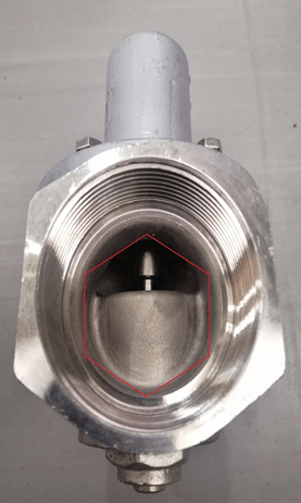
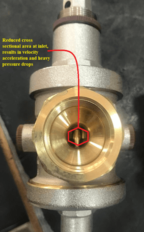
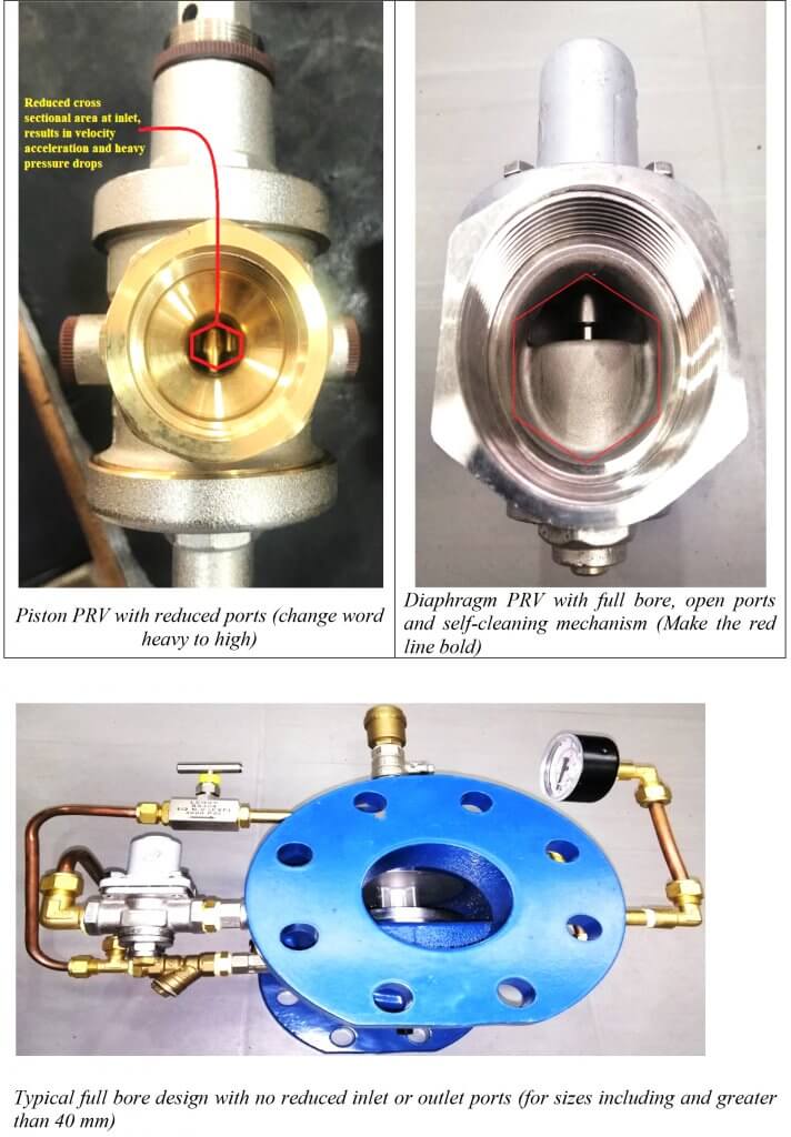
Each PRV’s internal construction varies from manufacturer to manufacturer, but little to no thought is given to check the orifice of different PRVs. This directly relates to problems in water starving due to restricted flows, high pressure drops with varying flows and velocity accelerations – all of which are grave problems in a Water System.
The pointers and comparisons are to create awareness because a problem in PRV design and selection puts the entire Utility Service design at a risk and can cause it to malfunction.
The table gives a comparison with respect to flow rates between both the PRV Models for line sizes of 50mm, 80mm and 100mm. Higher diameter lines are taken for the example, as normally PRVs are installed on the ring
| Line Size
(mm) |
Piston PRV X | Diaphragm PRV | ||
| Cv | Kv (cum/hr) | Cv |
Kv (cum/hr) |
|
|
50 |
20.8 | 18 | 52.7 | 45.6 |
| 80 | 31.25 | 27 | 64.1 |
55.4 |
| 100 | 45.13 | 39 | 100.2 |
86.6 |
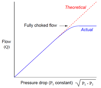
The coefficient of Cv is used by Engineers to size the valves. In layman’s terms you need an orifice which is big enough for the water to go through. If the orifice is too small, it can cause a pressure drop that makes the water drop below its vapour pressure. If the water drops below its vapour pressure there would be implosions that damage the valve trims and cause wear on account of Cavitation.
In effect, the actual flow rate begins to deviate from what is predicted using the flow coefficient equation for sizing the Pressure Reducing Valves. That is because the vapour bubbles occupy more volume as the mass of water expands during the phase change (liquid to vapour), creating additional resistance to flow. The vapour bubble formation in the restricted orifice prevents the flow from increasing any further. The effect is called Choked Flow.
The main takeaway from the above values is that using a PRV (even if the size is the same as the line size) whose functional flow limits are outside the actual consumption flow rates, there would be issues of velocity acceleration and high-pressure drop that would result in water not reaching the farthest point, or in case of high demand – causing even more dire problems. The same case can be seen even if a PRV is manufactured with a reduced bore or has a much smaller opening on the inlet side.
Conclusions & Suggestions
- A PRV’s design must be based on the minimum and maximum flow rates.
- Cross-check the cross-sectional areas of the inlet, outlet, and body of the PRV.
- The National Building Code of India 2016 Section 2 Part 9, stipulates that Diaphragm operated PRV be always used. The PRV is to be installed on the by-pass line and strainers provided before the PRV.
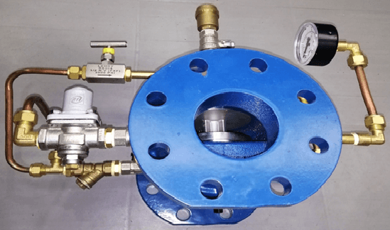
- For line sizes of 50mm and above, prefer a Pilot operated PRV that has a larger flow area and a feedback line for quicker response time to varying downstream pressures (directly proportional with demand).
- Consult the manufacturer for head loss-flow curves, cavitation chart, and Cv values before incorporating them into the design.


