- Where flow and pressure meets quality
- 044 42510000
- 044 42510001
- info@lehryvalves.com
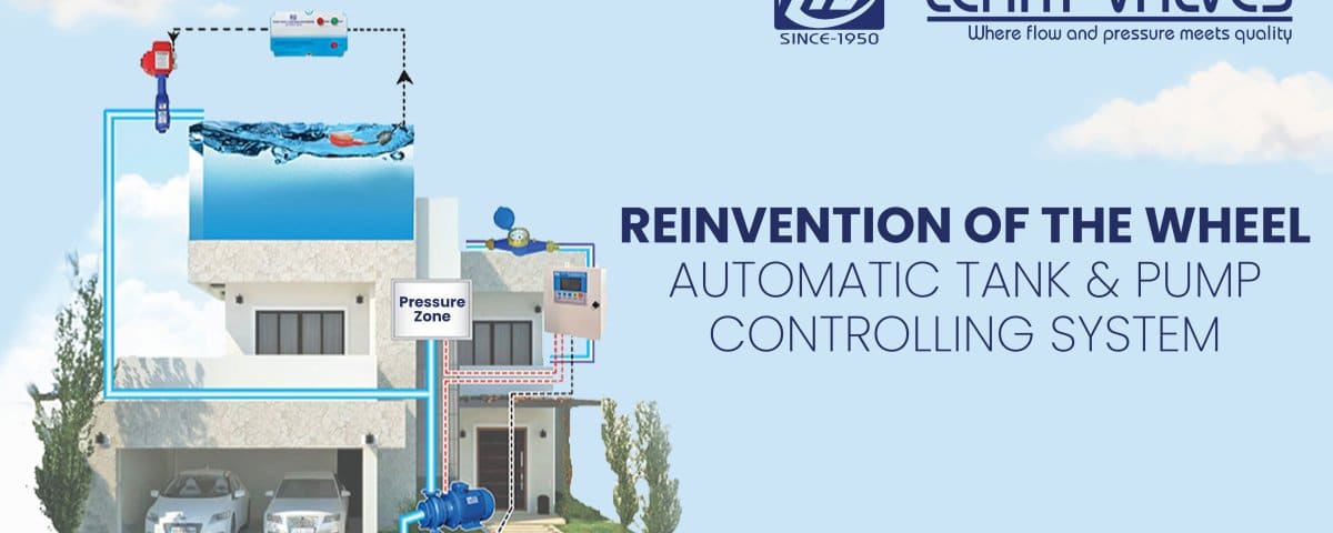
Automatic Tank & Pump Controlling system – Reinvention of the Wheel.

Case Study – Automatic Tank & Pump Control Systems
January 18, 2022
Case Study – Pressure Reducing Valves
April 13, 2022Automatic Tank & Pump Controlling system – Reinvention of the Wheel.
Introduction:
Ever since the Industrial revolution, we as a race have relied on and kept developing – machines & automation. Why? The answer is quite simple, it’s to reduce Work & Labor.
Decades later, and here we are still relying on them. Now comes an even serious issue of water conservation! Our tanks waste significant water when they overflow, due to either ignorance or just mere unawareness of the availability of level control systems.
A few age-old systems were introduced to automate tank filling, but until now they could not work alongside with the pump systems (rather with ease). Then, a change had to be called for – The reinvention of the wheel, if you may!
Working Principle – Tank Control:
Soon, the new tank controlling system was introduced by Lehry Valves, using just 3 simple components to put together a complete “system”. Working with very low energy, the system consists of a level float, a motorized valve and a control box. Based on the level of the tank, the valve would open and close through commands from the control box, with the float as an input. Water flow into the tank could thus be controlled. This set up could go on for N-number of tanks.
 |  |  |

- When tank level is low, the level switch will trigger the panel to open the motorized valve.
- When tank level is high, the level switch will trigger the panel to close the motorized valve.
Working Principle – Pump Control:
At the lower side – the pump side; Before only hydro-pneumatic pumps were designed to switch on/off depending on pressure levels on the line – a decrease in pressure level intimated that a there is no demand or an increase would intimate that water demand increased. The same logic could even be carried out in a conventional pump system.

- When the motorized valve closes, pressure in the line would increase & the pressure zone will trigger PLC panel to switch off pumps.
- When the motorized valve opens, pressure in the line would decrease & the pressure zone will trigger the PLC panel to switch on the pump(s).
By using a pressure zone and another control panel coupled with the pumps’ starter, the exact above operation could be carried out. Since the panel uses a PLC, pump selection couldn’t get easier. What’s more is, all pumps are utilized over a period of time, by using either a cycle-based operation / timer-based operation for pump selection.
Since a stagnant machine wouldn’t operate as efficiently as a regularly working on, the above usage of alternate pumps increases lifetime and maintains efficiency of the pumps.
Keeping up with technology and current needs, the system is under constant development for a greener-conserved tomorrow.
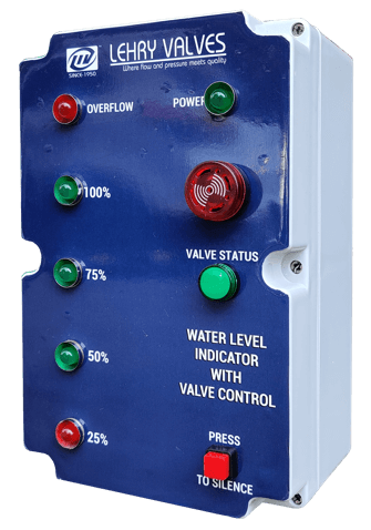
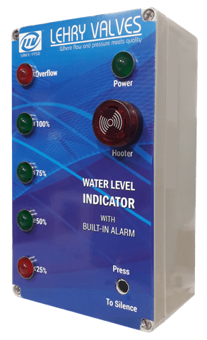
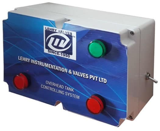
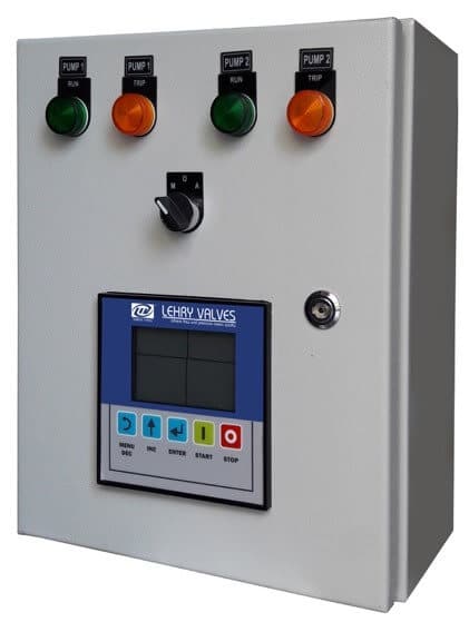
| 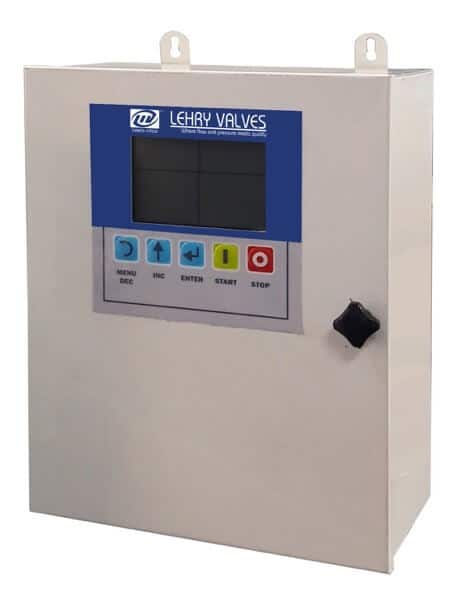 | 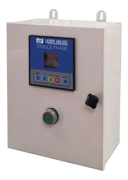 |
(HNS Panel) | (Premium Pump Smart Panel) | (Standard Type Panel) |
Overview / Conclusion:
When you think about tank automation, there are multiple solutions available. The only predicament many integrators used to have was the running of long wires from the tank to the pump, which had heavy cost implications, tedious troubleshooting and maintenance. Thanks to technological advances, we were able to come up with a solution of providing seamless independent operation of the tank and the pumps (in case of conventional transfer pumps). Bu using a motorized valve at the tank level to open / close depending on tank level, overflow or an empty tank is something you don’t ever have to worry about. Using pressure-based principles in the supply line, a provision of a pressure zone & a PLC panel integrated with the pump, we can accordingly automate the pump to either switch on or switch off automatically based on tank levels. Quite a simple system, with excellent ROI and most importantly, up to 15% average water savings.
![]()

3 Comments
What if it stops working due to which motor also not functioning. But if connected directly motor started to work.
What may be the problem
Hi,
Thanks for your message. The issue would most likely lie with the pressure switch/pressure transmitter installed at the pump side. We advise against a direct connection to the pump as it may cause the pump to fail due to inconsistent on-off cycles.
We will need more details to provide you with a report and solution, please drop a mail to marketing@lehryvalves.com and our regional team will get in touch with you ASAP.
That was very interesting and informative to learn the pump control systems. Thanks for the helpful article.