Water Conservation Through System Automation.
August 19, 2021
Case Study – Automatic Tank & Pump Control Systems
January 18, 2022Water Hammer Arrestor
A Solution for Water Hammering
Wondering why you hear a banging noise in the water supply pipeline? A banging noise in the pipeline can be heard in washrooms when you use a health faucet, a quick closing tap, flush valve, etc.
How do we rectify this issue??
Before we talk about rectifying the problem, let me share a quick overview of what is Water Hammering ?
-
Valve closed – static water flow
Here, with the valve in the pipe closed, the pipeline will have a static water flow condition. Hence, kinetic energy = 0

Fig 1 – static conditions
- Valve open – moving /dynamic water flow
When the valve is opened, the water starts flowing in the pipeline. Here, we can measure the kinetic energy of the flowing water by using the formula: KE = (m*v²)/2; where m is mass, v is velocity of the water.

Fig 2 – dynamic conditions
- The valve closes – water hammering (quick closing)
 Fig 3 – condition when valve is closed suddenly
As the valve is suddenly closed, the flowing water with its energy (as explained with the above formula) hits the valve, bounces back and collides with the approaching stream of water. The collision that happens in the pipeline triggers an enormous pressure spike in the pipeline to create this undesirable noise and shaking, called water hammering. (Think of a train engine applying a sudden brake causing the compartments to collide with each other).
Here, the rise in pressure inside the pipeline could be measured using Joukowsky’s Formula. Pressure rise, pr=w*a*v/144g ; where w is specific gravity of liquid, a is velocity of pressure wave in m/s, v is change in flow velocity in m/s, g is gravitational constant.
or P= δp = C*ρ*U ; where C is sonic velocity of the wave front, P change in pressure(δp), ρ is density of liquid, U is change in momentum
WATER HAMMER ARRESTOR
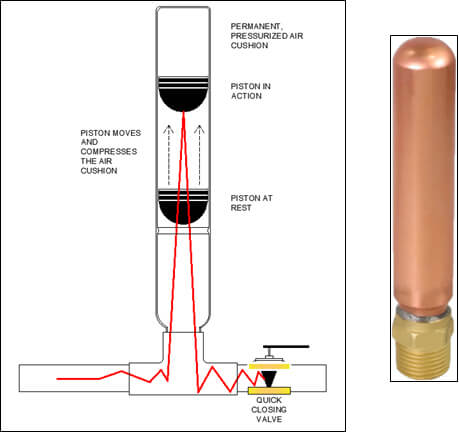
Fig 4 – Water hammer arrestor
The picture shown here illustrates how a Water Hammer Arrestor functions. This simple device can effectively control the undesirable effects of water hammering and is widely being used in the industry. The operations of the WHA can be compared to the working of a shock absorber used in a motorbike.
The pressure shock wave, with its energy hits and pushes the piston inside the WHA upwards, compressing the pre-charged air and loses its energy. Once the effect of the peak pressure shock wave is absorbed, the piston gradually returns back to its original rest position. This tendency of the piston inside the water hammer arrestor to revert to its original position is the reason behind the working of a water hammer arrestor.
Graph showing water pressure against passage of time:

Fig 5 – Graph showing water pressure against time
As per the example used here, a standard 1/2″ supply line with water flowing at 1.8 m/s can generate a pressure rise of 29 kg/cm2 above the flow pressure itself. The resultant shock wave bounces back and forth within the supply line until it reaches a point of relief in a larger main where the velocity is much slower.
The peak spike of the water hammering effect could even reach up to 6 times that of the nominal flow pressure.
Installation:

Fig. 6
Rule 1: Covers multiple fixture branch lines which do not exceed 20 ft. (6m) in length.
Rule 2: Covers multiple fixture branch lines which exceeds 20 ft. (6m) in length.
Codes and Standards

609.10 Water Hammer: Building water supply systems where quick-acting valves are installed shall be provided with water hammer arrester(s) to absorb high pressures resulting from the quick closing of these valves. Water hammer arresters shall be approved mechanical devices that comply with ASSE 1010 or PDI-WH 201 and shall be installed as close as possible to quick-closing valves.

604.9 Water hammer: The flow velocity of the water distribution system shall be controlled to reduce the possibility of water hammer. A water-hammer arrestor shall be installed where quick-closing valves are utilized. Water-hammer arrestors shall be installed in accordance with the manufacturer’s instructions. Water-hammer arrestors shall conform to ASSE 1010. WATER-HAMMER ARRESTOR. A device utilized to absorb the pressure surge (water hammer) that occurs when water flow is suddenly stopped in a water supply system

Fig 7 – different installations
Selection procedure:
The water hammer arrestor is selected based on the number and type of fixture units as below.
| All units are in millimeter (mm) | |||||||
| SIZE | A (I.D) |
B (H.D) |
C (Hex) |
WEIGHT (Gm) |
FIXTURE UNITS | PDI STANDARD |
|
| 1/2″ | 15mm | 14.5 | 129 | 21 | 115 | 1-3 | AA |
| 1/2″ | 15mm | 14.5 | 151 | 21 | 170 | 1-11 | A |
| 3/4″ | 20mm | 19.5 | 185 | 27 | 248 | 12-32 | B |
| 1″ | 25mm | 25 | 221.5 | 34 | 409 | 33-60 | C |
| 1 1/4″ | 32mm | 33 | 259 | 43 | 755 | 61-113 | D |
| 1 1/2″ | 40mm | 39 | 283 | 49 | 940 | 114-154 | E |
| 2″ | 50mm | 51 | 328 | 61 | 1140 | 155-330 | F |


